Sunday, May 30, 2010
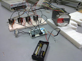
Initial Design for Controlled Circuit
Four of the darling ton transistors (TIP122) are located on the breadboard. A heat sink will be installed at each of the darling ton transistors. The reason for installation because darling ton transistor will produce a lot of heats. Transistor itself cannot stand for too high temperature, so it needs the help of heat sinks, heat can be eliminated. Inductance glue has to be included in between heat sink and transistor. Each of the darling ton transistors got three pins, which are base, collector and emitter. Base connects with the PORTD(s) in the microcontroller, collector connects with the diode (from positive to negative) to the ground port and emitter direct connect to the ground port. 24 V dc power supply will be used to supply the power to energise the coils inside the stepper motor. Each of the stepper motor will have a few of wires. The connection for each wire will be different. For the stepper motor (PK268-02B) that used for initial design, it have four wires which have to connect to collector pin for each transistor and the others two wires will be connected to the power port. PK268-02B has six types of colour wires, which are black, yellow, green, red, white and blue. Yellow and white wire will be connected to the power port while the others will be connected to the collector pin for each transistor. The sequences to connect the wires have to follow the programming that used for run the stepper motor and must be connected correctly.


Subscribe to:
Post Comments (Atom)

No comments:
Post a Comment